C L O S E D S Y S T EMS
I N T R O DU C T I ON
Through leaks, spills, and ventilation, an “open” solvent-using system
will release solvent vapors directly into the laboratory environment.
This introduction may be reduced by adding several key components
to the typical system. These items are:
A properly sealed solvent reservoir with ventilation control
A solvent waste container with secure fluid connections
A carbon filter to reduce vapors escaping the waste
container
1A
SOLVENT RESERVOIR FLUID CONNECTIONS
For a closed system on a bottle, each container first requires a
bottle cap with ports to fit the specific tubing sizes. When using caps
with threaded ports for fittings, the fittings may be selected and
replaced to accommodate different diameters of tubes. Caps with
“slip-through” ports (non-threaded holes drilled or molded into a cap)
are acceptable, provided the holes fit the tubing sizes securely. Most
slip-through caps are made to accommodate 1/8” or 1/16” OD.
1B
SOLVENT RESERVOIR AIR INLET
In systems where sparging is not employed, to complete the closed
system on a bottle each container requires a device to control the
bottle cap vent. A closed bottle must function exactly like a coffee
travel mug -- liquid goes out through one hole, and air comes in
through a pinhole to displace the liquid removed. To manage the air
flow, the simplest answer is a check valve assembly made to occupy
a bottle cap port. The check valve allows air to enter a bottle as the
pump moves the liquid phase out to the system. It also minimizes
escape of vapors contained in the bottle. Should the bottle ever be
exposed to pressure -- a result of a rise in lab temperature (over
a warm weekend, for example) or a sparging line accidentally con-
nected -- to reduce the threat of explosion a check-and-relief valve
assembly is also available. The relief function allows pressure to
escape while still preserving a “pressure blanket” of 0.5-1psi in the
bottle. Although VapCheck
TM
units resist many standard solvents,
care should be taken to consider the chemical compatibility of a sol-
vent with VapCheck
TM
materials.
2A
WASTE CONTAINER FLUID CONNECTIONS
Many labs are standardizing on Justrite
®
2- and 5- gallon HPLC Cen-
tura
TM
waste containers. These safety cans have enough capacity
for days or weeks of typical flow, vent automatically at 5 psig if pres-
surized, and allow users to disengage waste lines and vapor filters
quickly during waste collection. Containers are available with either
Polypropylene or Stainless Steel quick disconnects. Care should
be taken when choosing the disconnect type. For example, at high
concentrations the solvent Hexane swells Polyproplyene as much
as 30%, causing the disconnect to “stick” and restrict fluid flow.
Containers and manifolds with stainless steel quick disconnects are
advised wherever such chemical compatiblity issues may arise; con-
sult a chemical compatibility guide before selecting a container. One
should also note that Justrite containers must be grounded while in
use and especially while emptying the container, as static electricity
has been known to ignite solvent fumes.
For labs which choose not to use Justrite
®
containers, Vaplock
TM
prod-
ucts are also available to adapt to standard drum and pail closures,
as well as Nalgene
®
83B, 53B, and 100-415 carboys. PLEASE NOTE
THAT IT IS NOT POSSIBLE TO GROUND DRUM, PAIL, GLASS BOTTLE
AND CARBOY (NON-JUSTRITE
®
) CONTAINERS; THIS MAY RESULT IN
A SAFETY HAZARD WITH FLAMMABLE SOLVENTS.
The type and dimension of waste tubing found on an HPLC varies
widely, depending on both system and user requirements. Outer
and inner diameters range from microns to inches, and tubing
material may be hard- or soft-wall plastic, metal, smooth-walled or
corrugated. All these lines must be connected to a waste container.
Adapting securely, without leaks and vapor release, poses a problem
when attempting a closed system. VapLock
TM
manifolds adapt to
tubing sizes up to 1/2” ID or OD (and larger if necessary) and can be
stacked to accept additional lines. Most manifold ports permit direct
connection of 1/4” or 1/2” threaded NPT fittings.
2B
WASTE CONTAINER VAPOR VENT
The most significant vapor generator in an HPLC system is the waste
can, where solvents draining to the container may volatilize rapidly
as solvent entering the container forces vapor into the laboratory.
Activated carbon has excellent adsorptive properties for organic sol-
vents. With a Gas Chromatograph, a number of carbon types were
tested for vapor breakthrough under a flow of Acetonitrile vapor, one
of the more common solvents used in HPLC. After determining the
appropriate type, the carbon was similarly tested on other common
solvents. The breakthrough data published in this brochure is based
on use of 100% concentration of each solvent, at a flow rate of 1
mL per minute at S.T.P. (most analytical HPLCs run at 1-2 mL per
minute). Disposal of spent cartridges should be conducted in accor-
dance with local safety codes.
P U R C H A S E F R O M :
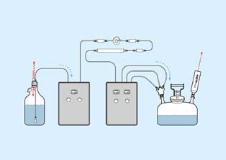
1: Solvent Reservoir A: Fluid Connections
2. Waste Container B: Air inlet (1) or vent (2
EXAMPLE OF A CLOSED SYSTEM HPLC
PUMP
DETECTOR
A
B
1
2
B
A
VapLock
TM
and VapCheck
TM
are Trademarks of Western Fluids Engineering & Mfg, LLC
Teflon
®
, Tefzel
®
, Viton
®
, and Delrin
®
are Trademarks of E.I. du Pont de Nemours and Company
Safety Eco Funnel
TM
is a trademark of CP Lab Safety
Kel-F
®
is a Registered Trademark of the 3M Company
PEEK
TM
polymer is a Trademark of Victrex PLC
Justrite
®
and Centura
TM
are Trademarks of Justrite Manufacturing
Nalgene
®
is a Trademark of Nalge Nunc International
Duran
®
is a Trademark of Schott AG
P R I C E S S U B J E C T T O C H ANG E W I T HOU T NO T I C E
For information regarding your local distributor, please contact:
+ 1 . 9 5 1 . 4 7 1 . 2 5 1 1 [ t e l ]
+ 1 . 9 5 1 . 4 7 1 . 2 1 0 7 [ f a x ]